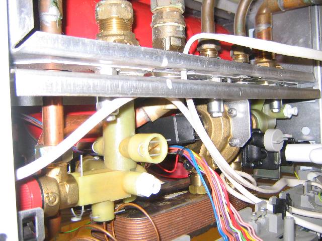
Diverter Valve / Diaphragm Replacement on the
Worcester Bosch 24CDi (and variants) Combi Boiler
The manual covers the 24CDi, 28CDi and 35CDi hence the innards as far as the parts that concern us are the same.
The diverter valve contains a rubber diaphragm which sits inline with the hot water (DHW) supply. When a hot tap is opened, the diaphragm shifts sideways due to the pressure differential and in doing so diverts the primary water circuit through the secondary heat exchanger (rather than the radiators) and activates a microswitch to fire up the boiler.
It is fair to say that you might want to consider replacing the whole diverter valve rather than just the diaphragm as given you'll be saving so much on labour by DIYing it you'll still be quids in. Furthermore, it's one less thing to worry about if you can reset the clock on when the valve itself might fail in the future. Note also that you really must get yourself an o-ring and washer pack as any dismantling of the boiler will reveal that these compress over time as they seat/bed themselves in - reassembly will otherwise invariably end in tears as you find leaks springing up everywhere!
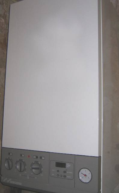
Worcester Bosch 24CDi RSF Combination Boiler
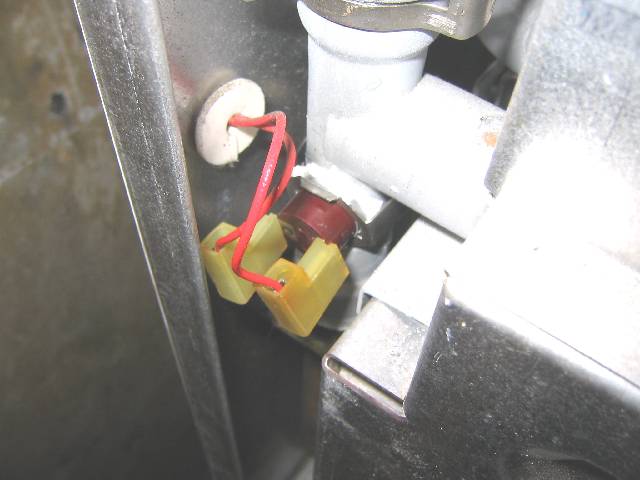
The Central Heating Thermister. Not only is this used to control the boiler output to maintain the preset temperature of the primary circuit but it also controls the pump/fan in the case of overrun. Overrun is the case where the boiler continues to heat up following CH/DHW demand as a result of now-static hot water in the primary circuit. In my case this overrun control was particularly erratic and would cause the fan to oscillate. This turned out to be due to the thermister not being positioned correctly on the pipe - I readjusted this and added thermal heatsink compound to improve the thermal connection- this solved the problem.
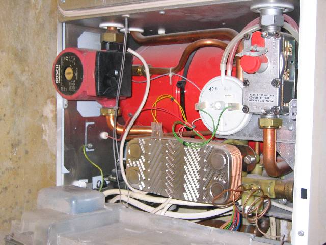
Boiler with front panel removed. As you can it's all quite daunting and, as (bad, yet typial) luck would have it, the majority of this needed disconnecting/removing in order to get at the diverter valve!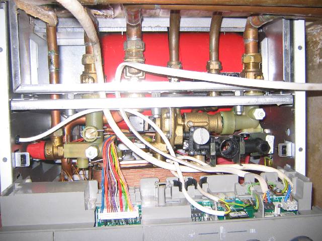

Underside of boiler. The water, gas and CH flow/return can all be isolated here to enable servicing of the boiler. Two drain taps (flow and return) are also fitted here - use them once the boiler is isolated as there're 10+ litres of pressurised water in the expansion tank to get rid of before you start undoing anything! This avoids the need to drain the whole system and the subsequent addition of inhibitor that would be required.
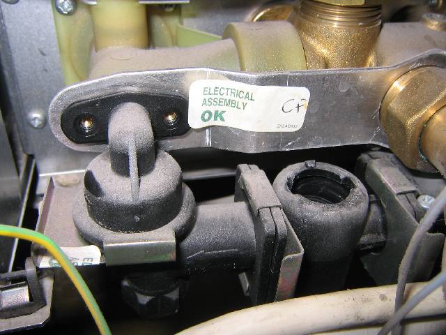
Filling Loop. Once the two securing screws are removed the assembly can be removed by easing the loop/diverter connection apart. Be aware of the small o-ring between the filling loop and securing plate. With regards to o-rings you will find these have been used on numerous pipe joints in the boiler. In ALL cases these must be replaced with new rings or else you run the risk of leaks where the o-ring has deformed into it's old orientiation yet been replaced in a new one. New rings should be lubricated with silicone grease to minimise damage when reassmebling, help with their seating and prolong their life.
[Edit: It would appear that some more recent version of the CDi range may well have a filling loop that looks different to this, in particular that the retaining bracket that attaches it to the diverter is no longer present. Whatever you have, just remember how it fits and how you got it out. As Haynes manuals like to say: 'refitting is the reversal of removal'!] 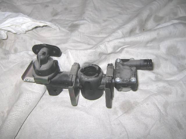
Filling Loop removed from boiler.

Water-to-Water Heat Exchanger removed from boiler. This was removed by undoing the main nut connecting it to the diverter valve in addition to removing the jubilee clip and screw from the return flow manifold. The other two ports connect to the boiler merely by sliding in to female unions relying on the o-rings to provide a seal. You can see in the middle port (DHW inlet) that there is a flow limiter to reduce the hot water flow - remove this and clean as this may well have debris in it. For all ports, new o-rings/washers are required as necessary.
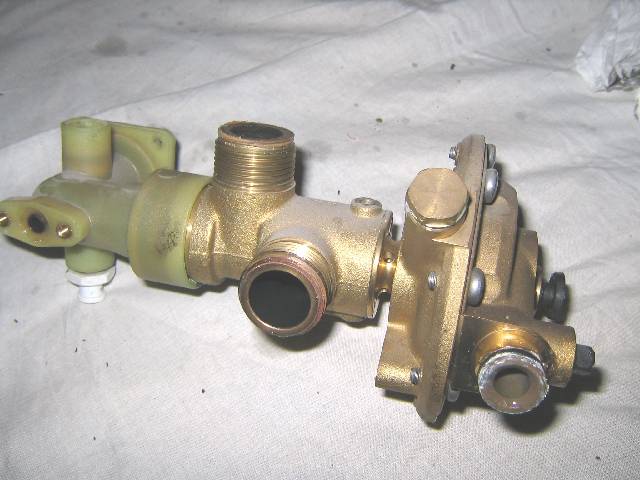
Diverter Valve removed from boiler. Once the filling loop, water-to-water heat exchanger and bypass tube are removed this can be unscrewed from the boiler. It connects via pipes with o-rings again so these need replacing and ring recesses cleaning to ensure a secure fit. The diaphragm is contained within the housing on the right of the valve. The left plastic manifold can be removed if necessary however I kept it in place as the joint was secure.. 'Why fix it if it ain't broke'?!
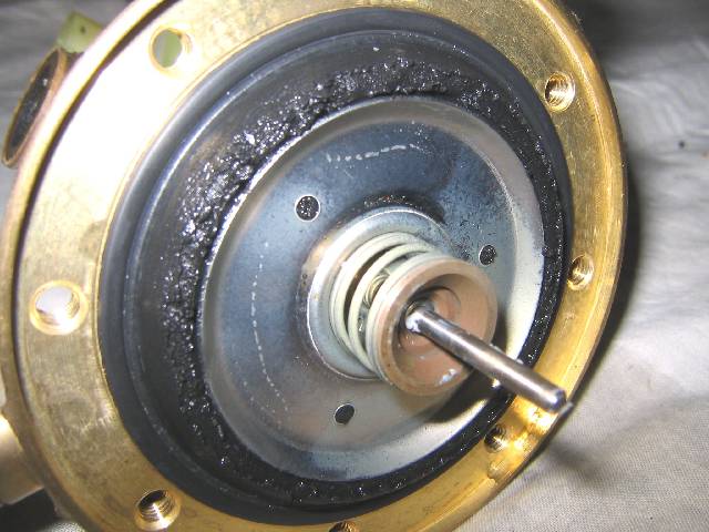
Diaphragm as found following removal of the valve cover.
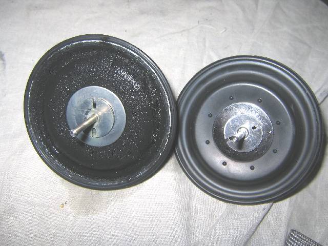
Comparison of the old and new diaphragms. It is clear to see how badly perished the existing diaphragm was and indeed it had a couple of holes in it which will have reduced the pressure differential either side of the disc resulting in a partial failure of the valve function. The shaft of the new diaphragm required lubricating with silicone grease before refitting and care should be taken to balance/centre the diaphragm on the shaft to ensure it is held centrally in the valve body.
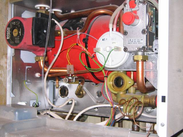
The boiler with its 'guts' removed. Now is the time to clean all the mating surfaces and replace the existing o-rings.
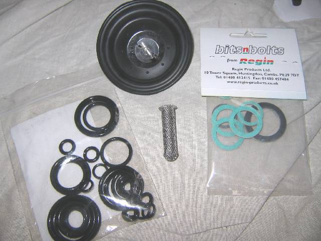
The replacement parts for this job - diaphragm, inlet strainer (my diverter valve didn't have one originally fitted however I retrofitted this as per the valve manufacturers advice), o-ring pack (a Worcester spare item) and generic pack of fibre washers.
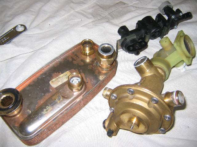
The removed parts cleaned up, reassembled and ready for refitting. The mating faces were all cleaned with wire wool however make sure you flush all components if doing this to ensure no fibres remain inside.
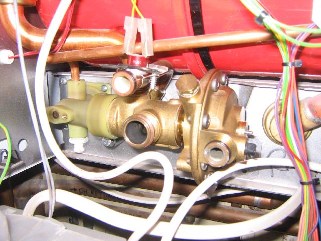
The diverter valve and manifold refitted. Note the DHW thermistor at the top of the picture - this may require reseating and new heatsink compound if this has been disturbed during the removal of surrounding parts.
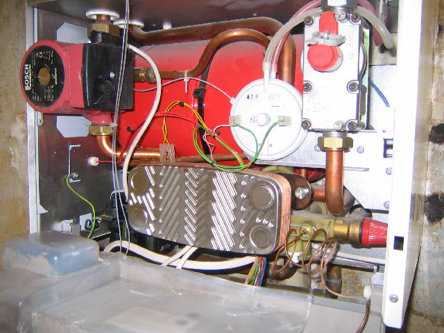
Lastly, the water-to-water heat exchanger fitted!
|
